
![]()
Let’s start with a look at my simple networking configuration. This is how my lab environment looks at present. I have created a vSphere distributed switch and created 3 distributed portgroups. The management network is on a public VLAN 51. This is where my vCenter server and ESXi hosts reside, and is also the network on which the Supervisor cluster nodes / virtual machines are deployed. The workload network, which is the network on which the TKG cluster nodes / virtual machines are deployed, is a distributed portgroup on a different VLAN 50. Note that the Supervisor cluster nodes / virtual machines are also plumbed up with an additional interface on the workload network. Finally, the frontend network, used by HA-Proxy to provide load balancer functionality, is a distributed portgroup on the same VLAN 50.


Let’s now revisit the prerequisites, and adding some possible values where needed.
- Make sure that both DRS and HA are enabled.
- If not using NSX-T, create a vSphere Distributed Switch (VDS) for all the hosts in the cluster.
- Make sure that you have your desired Storage Policy created for the Supervisor Cluster VMs.
- Create a Content Library for HA-Proxy OVA. The HA-Proxy OVA needs to be added to this Content Library and deployed from there. (HA-proxy v0.1.7 can be downloaded from this link). A new v0.1.18 version with some fixes can be downloaded from here.
- Create a Content Library for TKG images. This Content Library is used to store the virtual machine images that will be used for deploying the TKG cluster virtual machines. Use the TKG subscription URL for these images.
- Identify an FQDN and a static IP address for HA-Proxy on the Management network. (My example uses haproxy.rainpole.com and 10.27.51.134 / VLAN 51). Note that this address must be specificied in a CIDR format that matches your subnet mask. As I have a /24 network and my subnet mask is 255.255.255.0, the address is specified as 10.27.51.134/24.
- Identify a static IP address for HA-Proxy on the Worker network. (My example uses 192.50.0.134 / VLAN 50). Again, this must be specified in a CIDR format, so again, since this is a /24 network, the address is 192.50.0.134/24.
- (Optional) Identify a static IP address for HA-Proxy – Frontend network. (My example uses 192.50.0.170 / VLAN 50).
- Identify a range of IP addresses for the Supervisor VMs on Management network. (My example uses 10.27.51.191 – 10.27.51.194 / VLAN 51). Note that the HA-Proxy looks for a CIDR, and this must start and stop on a CIDR boundary. If you need to figure out what range of IP addresses maps to a CIDR, consider using a CIDR Calculator, e.g. https://www.ipaddressguide.com/cidr
- Identify a range of IP addresses for the Workload network. These will be used by both the Supervisor control plane nodes, as well as nodes that are provisioned for TKG “guest” clusters. (My example uses 192.50.0.184-192.50.0.199 – a range of 16 IP addresses / VLAN 50).
- Identify a range of IP addresses for Load Balancers – these can be on either the Workload network or optionally on the Frontend network. (My example uses 192.50.0.176/29 – a range of just 8 IP addresses / VLAN 50). As you can see, this is specified as a CIDR once more, so you need to ensure that this starts and ends on a CIDR boundary. The CIDR Calculator mentioned above will help you to determine if this is indeed the case.
HA-Proxy deployment
These are the steps to provision the HA-Proxy. I have not shown how to create the content library, or how to add the HA-Proxy OVA to the Content Library. These are very simple to do, and steps are available in the official documentation. Instead, I start from the provisioning of the HA-Proxy OVA in the Content Library.
Note: This procedure is using a non-release version of the product. Thus, some of the screenshots may change before GA. However, the deployment steps should remain the same.
As we mentioned in the prerequisites, there are 2 Content Libraries in the configuration, one for HAProxy and the other for the TKG images.

Open the HA-Proxy content library, select the HA-Proxy OVA Template and select “New VM from This Template…“:

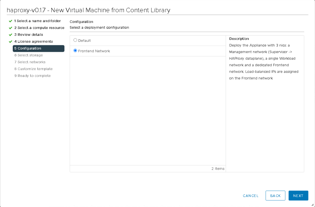
The initial part of the deployment (selecting name, folder, compute resources, etc.) are quite straight-forward once again so I have skipped forward to the configuration part. As mentioned in the “Getting Started” post, there are 2 options when deploying the HA-Proxy – it can be deployed with 2 NICs or 3 NICs.
In the 2 NIC configuration, there is a Management network and a Workload network. The Management network communicates with the Supervisor control plane whilst the Workload network is used for communicating to both TKG node IP addresses and providing Load Balancer IP addresses.
In the 3 NIC configuration, a third network is configured, called the Frontend network. This moves the Load Balancer from provisioning IP addresses on the Workload network to the Frontend network. In this example, I am using the Frontend network for the Load Balancer IP addresses, as shown in the networking diagram above. However, it is the same VLAN and subnet as the Workload network, so I need to be careful not to overlap the network ranges.
Next step is to select the storage on which to provision the HA-Proxy appliance. I’m going to place it on my vSAN datastore.

Now we get to the heart of the configuration. Here we determine which of our distributed portgroups map to the Management, Workload and Frontend networks. Refer back to my networking diagram at the beginning of the post for a visualization of my setup.
My management network is on VLAN 51, which is the same network where my vCenter server and ESXi hosts reside. The management network is also the network where the vSphere with Tanzu Supervisor control plane VMs / nodes are deployed.
The workload network is where the TKG cluster VMs / nodes are deployed, but as mentioned earlier, the Supervisor control plane VMs are also plumbed up on this network.
The load balancer network is where the load balancers (Supervisor API server, TKG API servers, TKG Load Balancer Services) are provisioned. Note that if the worker network and control plane network are on separate subnets or VLANs, they will need a route to each other. These networks cannot be isolated.
Finally, if you selected the 2 NICs configuration for the HA-Proxy, the Frontend setting is ignored on this screen. After setting the networks appropriately, click Next.

Now we come to the HA-Proxy appliance configuration. Provide a root password and decide if you want to leave root login enabled. I have chosen a very simple password. The TLS fields will be automatically generated if left blank.

In this network config window, provide network details about the HA-Proxy for the management network, the workload network and the optional frontend/load balancer network. These all require static IP addresses, in the CIDR format (in my case, these are /24). You will need to specify a CIDR format that matches the subnet mask of your networks. These should have all been noted down as part of the prerequisites. Populate both DNS and Gateway information for each of the networks.

Next, provide details about the Load Balancer range. These are the IP addresses that are used to bring up a frontend IP address for the Supervisor control plane API server, as well as the TKG “guest” cluster load balancer services and API server. The purpose of the load balancers are behave as virtual IP addresses, and to handle outages on one or more of the control plane components or Pods participating in a Service. In the event of a node or Pod failure, it is not visible to the end user, since the load balancer IP address will re-route to another back-end component for any requests.
In the prerequisites, you identified a range of IP addresses to use. Here I used 192.50.0.176/29 which provides 8 load balancer IP addresses from the range 192.50.0.176-192.50.0.183. This is sufficient for some simple testing. You may want to use a larger range. Again, use the CIDR calculator above to ensure that the range is on a CIDR boundary.
Also make note of the HA-Proxy Dataplane API management port of 5556. This will be required later, along with the HAProxy User ID and Password, when we enable vSphere with Tanzu.

Review the configuration and click Finish. The HA-Proxy will now deploy.

A useful tip to test HA-Proxy is to connect to the FQDN of the HA-Proxy on the management network using port 5556, and /v2 as the path. You should get prompted for HA-Proxy login credentials, but if it is all working you should observe a message similar to the following:

Another useful tip is to ssh to the HA-Proxy and check that the /var/log/cloud-init.log file reports that the setup was successful. It should have something similar to the following at the end:
2020-10-23 13:20:53,592 – handlers.py[DEBUG]: finish: modules-final: SUCCESS: running modules for final
If there are any failure messages on the last line, search the log file for “Traceback” or “FAIL” messages and see if you can address the issue.
All going well, at this point, the HA Proxy has been deployed and our environment should look something like this.

One final test that you might consider doing is verifying that the Load Balancer/Virtual IP Address range is now responding to pings. You could do a simple ping test of course, but I like to use an IP Scanner (e.g. https://angryip.org/) which is a quick way to check that the full range of IP addresses are available. Unless the Load Balancer IP Address range is responding, there is no point in proceeding to the next step of deploying vSphere with Tanzu.However, if everything has gone well, the Load Balancer IP addresses are available and we are ready to move on.
That covers the HA-Proxy deployment. In a future post, I will cover the remaining tasks.